
In the ever-evolving world of networking, organizations have faced the challenge of keeping up with the latest advancements in technology. Segment Routing (SR) is a relatively new and innovative technology that provides organizations with a more efficient, scalable and flexible alternative to MPLS Label Distribution Protocol (LDP). This article will explore the reasons why organizations should consider migrating from MPLS LDP to SR.
Multiprotocol Label Switching Label Distribution Protocol (MPLS LDP) has been the standard for routing protocols for many years, but with the advent of new technologies, such as Segment Routing (SR), it’s time for organizations to evolve. This article will explore the benefits and the key services that can be configured using SR.
Why Migrate to Segment Routing?
Segment Routing offers several benefits over MPLS LDP. Firstly, it’s simpler to manage and maintain, as it uses a more straightforward approach to routing, this results in reduced complexity and increased efficiency in network configurations.The traffic engineering capabilities also improve significantly with SR, as they allow for real-time, programmable and flexible control of the network traffic.
SR uses a source routing approach, where the entire path of the packet is defined by the source node and coded in the packet itself. This approach provides a more flexible and scalable solution compared to MPLS LDP, which uses a hop-by-hop approach to routing.In terms of scalability, SR offers improved it allows for the creation of multiple paths through the network, providing better traffic management and reducing the risk of network congestion.
In conclusion, SR is the future of networking, and it is essential for organizations to embrace this technology to remain competitive in the rapidly evolving digital landscape. With the combination of SDN platforms and the improved performance, scalability, and efficiency offered by SR, organizations are well-equipped to face the challenges of the future and provide the best possible services to their customers.

Basic Configuration of Segment Routing
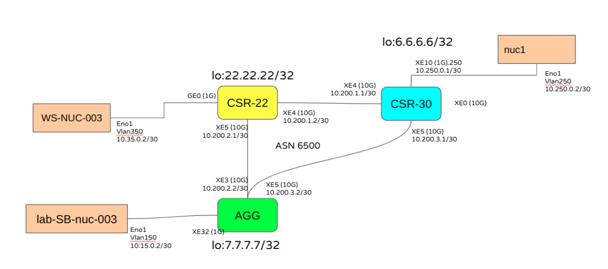
A ring with 3 devices running Segment running with OSPF as IGP as shown following topology:
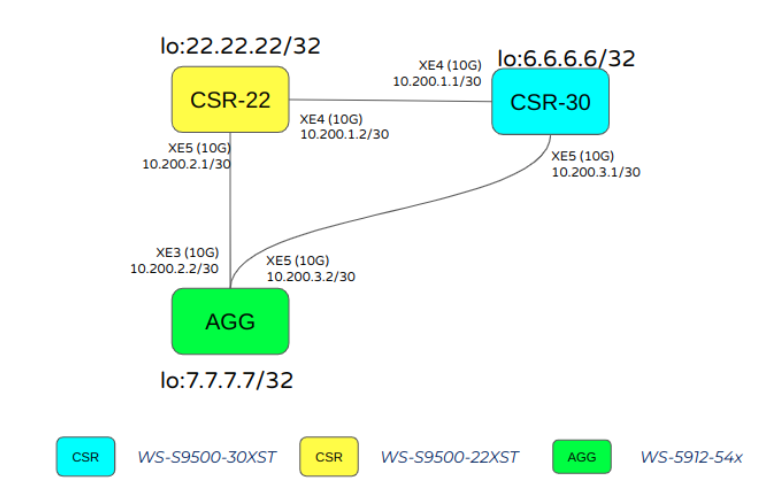
At Whitestack, we have deployed laboratories and tested the configuration and right operation of the most popular services configured in a typical MPLS LDP network. In this article we will show a lab that uses the following equipment:
| Hostname | OS /NOS | Hardware |
|---|---|---|
|
CSR30 |
OcNOS-5.1-SP-CSR |
Ufi Space S9500-30XS-P |
|
CSR22 |
OcNOS-5.1.201-SP_CSR |
Ufi Space S9500-22XST |
|
nuc001 |
OcNOS-5.1.173-SP_MPLS |
Edgecore 5912-54X-O-48V-F |
|
AGG |
Ubuntu 20.04.3 LTS |
Intel NUC6i3SYH |
|
lab-SB-nuc-003 |
Ubuntu 20.04 LTS |
Intel NUC6i3SYH |
|
WS-NUC-003
|
Ubuntu 20.04.3 LTS |
Intel NUC6i3SYH
|
And basic configuration of the network:
| Hostname | CSR22 | CSR30 | AGG |
|---|---|---|---|
|
OSPF Status |
router ospf 100 ospf router-id 22.22.22.22 network 10.100.0.0/30 area 0.0.0.0 network 10.200.1.0/30 area 0.0.0.0 network 10.200.2.0/30 area 0.0.0.0 network 22.22.22.22/32 area 0.0.0.0 ospf segment-routing global block 16000 23999 segment-routing mpls segment-routing prefix-sid-map advertise-local |
router ospf 100 ospf router-id 6.6.6.6 network 6.6.6.6/32 area 0.0.0.0 network 10.200.1.0/30 area 0.0.0.0 network 10.200.3.0/30 area 0.0.0.0 ospf segment-routing global block 30000 50000 segment-routing mpls segment-routing prefix-sid-map advertise-local |
router ospf 100 ospf router-id 7.7.7.7 network 7.7.7.7/32 area 0.0.0.0 network 10.100.100.0/30 area 0.0.0.0 network 10.200.2.0/30 area 0.0.0.0 network 10.200.3.0/30 area 0.0.0.0 ospf segment-routing global block 16000 23999 segment-routing mpls segment-routing prefix-sid-map advertise-local |
|
Network Interfaces |
interface xe4 ip address 10.200.1.2/30 mtu 9216 label-switching ip ospf network point-to-point interface xe5 ip address 10.200.2.1/30 mtu 9216 label-switching ip ospf network point-to-point |
interface xe4 ip address 10.200.1.1/30 mtu 9216 label-switching ip ospf network point-to-point interface xe5 ip address 10.200.3.1/30 mtu 9216 label-switching ip ospf network point-to-point |
interface xe3 load-interval 30 ip address 10.200.2.2/30 mtu 9216 label-switching ip ospf network point-to-point interface xe5 ip address 10.200.3.2/30 mtu 9216 label-switching ip ospf network point-to-point |
We can check OSPF status, SR capabilities and check labels allocated:
| Hostname | CSR22 | CSR30 | AGG |
|---|---|---|---|
|
OSPF Status |
CSR-LAB-S9500-22XST#show ip ospf neighbor Total number of full neighbors: 2 OSPF process 100 VRF(default): Neighbor ID Pri State Dead Time Address Interface Instance ID |
CSR-LAB-S9500-30XS#show ip ospf neighbor Total number of full neighbors: 2 OSPF process 100 VRF(default): Neighbor ID Pri State Dead Time Address Interface Instance ID 22.22.22.22 1 Full/ – 00:00:35 10.200.1.2 xe4 0 7.7.7.7 1 Full/ – 00:00:32 10.200.3.2 xe5 0 |
LAB-WSCL-PE001#show ip ospf neighbor Total number of full neighbors: 2 OSPF process 100 VRF(default): Neighbor ID Pri State Dead Time Address Interface Instance ID 22.22.22.22 1 Full/ – 00:00:33 10.200.2.1 xe3 0 6.6.6.6 1 Full/ – 00:00:33 10.200.3.1 xe5 0 |
|
OSPF SR capabilities |
CSR-LAB-S9500-22XST#show ip ospf segment-routing capability OSPF process 100: Advertisement Router Capability :6.6.6.6 Advertisement Router Capability :7.7.7.7 Advertisement Router Capability :22.22.22.22 |
CSR-LAB-S9500-30XS#show ip ospf segment-routing capability
OSPF process 100: Advertisement Router Capability :6.6.6.6 Algorithm0 :0 SRMS Preference :200 Total SID’S Supported :20001 SID Range List Count :1 SID’s Range :30000 – 50000 Advertisement Router Capability :7.7.7.7 Algorithm0 :0 SRMS Preference :128 Total SID’S Supported :8000 SID Range List Count :1 SID’s Range :16000 – 23999 Advertisement Router Capability :22.22.22.22 Algorithm0 :0 SRMS Preference :200 Total SID’S Supported :8000 SID Range List Count :1 SID’s Range :16000 – 23999
|
LAB-WSCL-PE001#show ip ospf segment-routing capability OSPF process 100: Advertisement Router Capability :6.6.6.6 Algorithm0 :0 SRMS Preference :200 Total SID’S Supported :20001 SID Range List Count :1 SID’s Range :30000 – 50000 Advertisement Router Capability :7.7.7.7 Algorithm0 :0 SRMS Preference :128 Total SID’S Supported :8000 SID Range List Count :1 SID’s Range :16000 – 23999 Advertisement Router Capability :22.22.22.22 Algorithm0 :0 SRMS Preference :200 Total SID’S Supported :8000 SID Range List Count :1 SID’s Range :16000 – 23999 |
|
Labels Forwarding-table |
CSR-LAB-S9500-22XST#show mpls ilm-table Codes: > – installed ILM, * – selected ILM, p – stale ILM K – CLI ILM, T – MPLS-TP, s – Stitched ILM S – SNMP, L – LDP, R – RSVP, C – CRLDP B – BGP , K – CLI , V – LDP_VC, I – IGP_SHORTCUT O – OSPF/OSPF6 SR, i – ISIS SR, k – SR CLI P – SR Policy, U – unknown
Code FEC/VRF/L2CKT ILM-ID In-Label Out-Label In-Intf Out-Intf/VRF Nexthop LSP-Type O> 22.22.22.22/32 1 16005 Nolabel N/A N/A 127.0.0.1 LSP_DEFAULT B> evpn:2222 3 640 Nolabel N/A N/A 127.0.0.1 LSP_DEFAULT B> evpn:2222 2 16 Nolabel N/A N/A 127.0.0.1 LSP_DEFAULT B> evpn:5050 4 17 Nolabel N/A N/A 127.0.0.1 LSP_DEFAULT B> evpn:5050 5 641 Nolabel N/A N/A 127.0.0.1 LSP_DEFAULT O> 10.200.2.2/32 6 24960 3 N/A xe5 10.200.2.2 LSP_DEFAULT O> 7.7.7.7/32 7 16007 16007 N/A xe5 10.200.2.2 LSP_DEFAULT O> 7.7.7.7/32 14 16007 30007 N/A xe4 10.200.1.1 LSP_DEFAULT O> 6.6.6.6/32 10 16006 30006 N/A xe4 10.200.1.1 LSP_DEFAULT O> 6.6.6.6/32 13 16006 16006 N/A xe5 10.200.2.2 LSP_DEFAULT P> 6.6.6.6/32 11 24320 16007 N/A xe5 10.200.2.2 LSP_DEFAULT B> vrf1 8 25664 Nolabel N/A vrf1 N/A LSP_DEFAULT O> 10.200.1.1/32 9 24961 3 N/A xe4 10.200.1.1 LSP_DEFAULT V> l2ckt:2596 12 26240 Nolabel xe5 ge0.60 N/A LSP_DEFAULT |
CSR-LAB-S9500-30XS#show mpls ilm-table Codes: > – installed ILM, * – selected ILM, p – stale ILM K – CLI ILM, T – MPLS-TP, s – Stitched ILM S – SNMP, L – LDP, R – RSVP, C – CRLDP B – BGP , K – CLI , V – LDP_VC, I – IGP_SHORTCUT O – OSPF/OSPF6 SR, i – ISIS SR, k – SR CLI P – SR Policy, U – unknown
Code FEC/VRF/L2CKT ILM-ID In-Label Out-Label In-Intf Out-Intf/VRF Nexthop LSP-Type O> 10.200.3.2/32 7 24320 3 N/A xe5 10.200.3.2 LSP_DEFAULT B> evpn:2222 3 640 Nolabel N/A N/A 127.0.0.1 LSP_DEFAULT B> evpn:2222 2 16 Nolabel N/A N/A 127.0.0.1 LSP_DEFAULT B> evpn:5050 4 17 Nolabel N/A N/A 127.0.0.1 LSP_DEFAULT B> evpn:5050 5 641 Nolabel N/A N/A 127.0.0.1 LSP_DEFAULT O> 22.22.22.22/32 9 30005 16005 N/A xe4 10.200.1.2 LSP_DEFAULT O> 22.22.22.22/32 13 30005 16005 N/A xe5 10.200.3.2 LSP_DEFAULT O> 10.200.1.2/32 6 24321 3 N/A xe4 10.200.1.2 LSP_DEFAULT B> vrf1 10 25024 Nolabel N/A vrf1 N/A LSP_DEFAULT O> 7.7.7.7/32 8 30007 16007 N/A xe5 10.200.3.2 LSP_DEFAULT O> 7.7.7.7/32 12 30007 16007 N/A xe4 10.200.1.2 LSP_DEFAULT O> 6.6.6.6/32 1 30006 Nolabel N/A N/A 127.0.0.1 LSP_DEFAULT V> l2ckt:2596 11 25600 Nolabel xe4 xe10.60 N/A LSP_DEFAULT V l2ckt:2597 14 25601 Nolabel xe5 xe10.60 N/A LSP_DEFAULT |
LAB-WSCL-PE001#show mpls ilm-table Codes: > – installed ILM, * – selected ILM, p – stale ILM K – CLI ILM, T – MPLS-TP, s – Stitched ILM S – SNMP, L – LDP, R – RSVP, C – CRLDP B – BGP , K – CLI , V – LDP_VC, I – IGP_SHORTCUT O – OSPF/OSPF6 SR, i – ISIS SR, k – SR CLI P – SR Policy, U – unknown
Code FEC/VRF/L2CKT ILM-ID In-Label Out-Label In-Intf Out-Intf/VRF Nexthop LSP-Type O> 7.7.7.7/32 1 16007 Nolabel N/A N/A 127.0.0.1 LSP_DEFAULT B> evpn:2222 3 640 Nolabel N/A N/A 127.0.0.1 LSP_DEFAULT B> evpn:2222 2 16 Nolabel N/A N/A 127.0.0.1 LSP_DEFAULT B> evpn:5050 4 17 Nolabel N/A N/A 127.0.0.1 LSP_DEFAULT O> 22.22.22.22/32 7 16005 16005 N/A xe3 10.200.2.1 LSP_DEFAULT O> 22.22.22.22/32 12 16005 30005 N/A xe5 10.200.3.1 LSP_DEFAULT B> evpn:5050 5 641 Nolabel N/A N/A 127.0.0.1 LSP_DEFAULT O> 6.6.6.6/32 10 16006 30006 N/A xe5 10.200.3.1 LSP_DEFAULT O> 6.6.6.6/32 11 16006 16006 N/A xe3 10.200.2.1 LSP_DEFAULT O> 10.200.3.1/32 9 24321 3 N/A xe5 10.200.3.1 LSP_DEFAULT O> 10.200.2.1/32 6 24320 3 N/A xe3 10.200.2.1 LSP_DEFAULT B> vrf1 8 24960 Nolabel N/A vrf1 N/A LSP_DEFAULT V l2ckt:2597 13 25600 Nolabel xe5 xe32.60 N/A LSP_DEFAULT |
Segment routing can be a simple and effective solution for building transport networks, such as metro or access rings, as it eliminates the need for complex protocol stacks and reduces the configuration overhead. In terms of service configuration, Segment routing supports the same services as MPLS LDP, including L2VPN VPLS, VPWS services, multicast for IPTV services, and L3VPN services. The difference is in the way these services are configured and signaled.
The following sections will detail the configurations and status checks for these services.
Key Services Configured using Segment Routing
SR can support the same service as MPLS LDP networks, including L2VPN VPLS, VPWS, multicast for IPTV and L3VPN services, and allow interoperability between them, facilitating the migration from MPLS to SR.
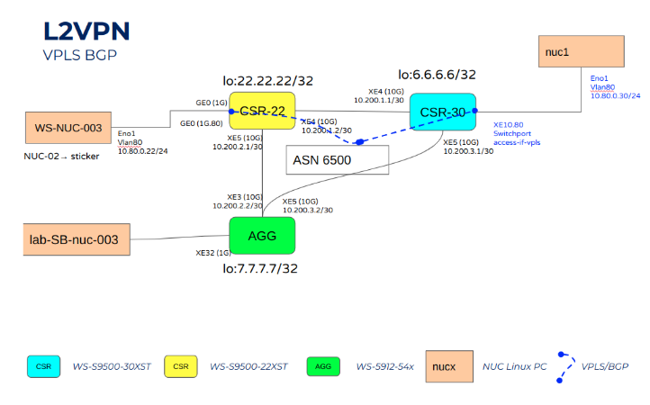
L2VPN VPLS setup over SR
L2VPN VPLS allows organizations to create a virtual private network between two or more sites, using a Layer 2 VPN. VPWS uses a Point-to-Point VPN, providing a secure and efficient connection between two sites.
In the example we will configure a VPLS service signaled with BGP.
| Hostname | CSR22 | CSR30 |
|---|---|---|
|
VPLS Definition |
mpls vpls VPLS-BGP 8080 |
mpls vpls vpls80 8080 |
|
BGP Configuration |
router bgp 65056 10.100.100.2 ..S.. 1 10.200.2.2 10006 xe5 2 110 2 |
router bgp 65056 |
|
Access Interface |
interface ge0.80 switchport |
interface xe10.80 switchport |
For testing, the iperf version 2.0.13 software has been used as it is a simple and easily replicable tool that requires few resources to be deployed. The following table shows the flow description used:
| Hostname | Role | FLOW-ID | Source | Destination | Protocol | BW | Iperf Command |
|---|---|---|---|---|---|---|---|
|
WS-NUC-003 |
Sender |
Flow 1 |
10.80.0.22 |
10.80.0.30 |
UDP
|
800M |
iperf -c 10.80.0.30 -u -i 1 -b 800M -t 1000 -e
|
|
nuc1 |
Receiver |
Flow 1 |
10.80.0.22 |
10.80.0.30 |
UDP
|
800M |
iperf -s -u -i 1 -B 10.80.0.30 -e |
and it is possible to check the results in sender and receiver.
Server:
whitestack@WS-NUC-003:~$ iperf -c 10.80.0.30 -u -i 1 -b 800M -t 1000 -e
Client connecting to 10.80.0.30, UDP port 5001 with pid 238308
Sending 1470 byte datagrams, IPG target: 14.02 us (kalman adjust)
UDP buffer size: 208 KByte (default)
[ 3] local 10.80.0.22 port 48583 connected with 10.80.0.30 port 5001
[ ID] Interval Transfer Bandwidth Write/Err PPS
[ 3] 0.0000-1.0000 sec 100 MBytes 839 Mbits/sec 71332/0 71331 pps
[ 3] 1.0000-2.0000 sec 100 MBytes 839 Mbits/sec 71328/0 71328 pps
[ 3] 2.0000-3.0000 sec 100 MBytes 839 Mbits/sec 71335/0 71332 pps
[ 3] 3.0000-4.0000 sec 100 MBytes 839 Mbits/sec 71331/0 71335 pps
[ 3] 4.0000-5.0000 sec 100 MBytes 839 Mbits/sec 71332/0 71329 pps
[ 3] 5.0000-6.0000 sec 100 MBytes 839 Mbits/sec 71333/0 71336 pps
[ 3] 6.0000-7.0000 sec 100 MBytes 839 Mbits/sec 71331/0 71332 pps
[ 3] 7.0000-8.0000 sec 100 MBytes 839 Mbits/sec 71331/0 71328 pps
[ 3] 8.0000-9.0000 sec 100 MBytes 839 Mbits/sec 71331/0 71334 pps
[ 3] 9.0000-10.0000 sec 100 MBytes 839 Mbits/sec 71330/0 71329 pps
[ 3] 10.0000-11.0000 sec 100 MBytes 839 Mbits/sec 71331/0 71331 pps
Receiver:
whitestack@nuc001:~$ iperf -s -u -i 1 -B 10.80.0.30 -e
Server listening on UDP port 5001 with pid 2836830
Binding to local address 10.80.0.30
Receiving 1470 byte datagrams
UDP buffer size: 208 KByte (default)
[ 3] local 10.80.0.30 port 5001 connected with 10.80.0.22 port 48583
[ ID] Interval Transfer Bandwidth Jitter Lost/Total Latency avg/min/max/stdev PPS NetPwr
[ 3] 0.0000-1.0000 sec 100 MBytes 840 Mbits/sec 0.030 ms 0/71393 (0%) -/-/-/- ms 71388 pps
[ 3] 1.0000-2.0000 sec 100 MBytes 839 Mbits/sec 0.032 ms 0/71342 (0%) -/-/-/- ms 71332 pps
[ 3] 2.0000-3.0000 sec 100 MBytes 839 Mbits/sec 0.028 ms 0/71329 (0%) -/-/-/- ms 71332 pps
[ 3] 3.0000-4.0000 sec 100 MBytes 839 Mbits/sec 0.038 ms 0/71326 (0%) -/-/-/- ms 71328 pps
[ 3] 4.0000-5.0000 sec 100 MBytes 839 Mbits/sec 0.026 ms 0/71334 (0%) -/-/-/- ms 71342 pps
[ 3] 5.0000-6.0000 sec 100 MBytes 839 Mbits/sec 0.024 ms 0/71339 (0%) -/-/-/- ms 71340 pps
[ 3] 6.0000-7.0000 sec 100 MBytes 839 Mbits/sec 0.028 ms 0/71322 (0%) -/-/-/- ms 71317 pps
[ 3] 7.0000-8.0000 sec 100 MBytes 839 Mbits/sec 0.030 ms 0/71344 (0%) -/-/-/- ms 71331 pps
[ 3] 8.0000-9.0000 sec 100 MBytes 839 Mbits/sec 0.029 ms 0/71329 (0%) -/-/-/- ms 71334 pps
[ 3] 9.0000-10.0000 sec 100 MBytes 839 Mbits/sec 0.025 ms 0/71325 (0%) -/-/-/- ms 71338 pps
[ 3] 10.0000-11.0000 sec 100 MBytes 839 Mbits/sec 0.032 ms 0/71346 (0%) -/-/-/- ms 71327 pps
[ 3] 11.0000-12.0000 sec 100 MBytes 839 Mbits/sec 0.038 ms 0/71330 (0%) -/-/-/- ms 71326 pps
And for check the network status:
| Hostname | CSR22 | CSR30 |
|---|---|---|
|
VPLS Detail |
CSR-LAB-S9500-22XST#show mpls vpls detail |
CSR-LAB-S9500-30XS#show mpls vpls detail |
|
VPLS MAC Learning |
CSR-LAB-S9500-22XST#show mpls vpls mac-address 8080 b8ae.edea.3b52 ge0.80 |
CSR-LAB-S9500-30XS#show mpls vpls mac-address 8080 b8ae.edea.3b52 xe4 – 22.22.22.22 300 |
|
BGP L2VPN Information |
CSR-LAB-S9500-22XST#show bgp l2vpn vpls detail |
CSR-LAB-S9500-30XS#show bgp l2vpn vpls detail |
BGP based autodiscovery and signaling of VPLS tunnels can simplify the configuration process and eliminate the need for targeted LDP sessions between tunnel endpoints. By exchanging BGP NLRIs between VPLS routers, new sites can be added to existing VPLS without requiring adjustments to the configuration of all routers forming the VPLS.
The use of a route reflector can further simplify the process of adding new sites, as the router connecting the new site only needs to peer with the route reflector and no additional configuration is required on other routers. This eliminates the need for additional separate equipment and can improve scalability and availability.
Overall, BGP based VPLS can provide significant benefits over LDP signaled VPLS in terms of configuration simplicity and flexibility.
Multicast setup over SR
Multicast for IPTV services provides organizations with efficient and reliable multicast transport, ensuring IPTV content is delivered to users quickly and efficiently.
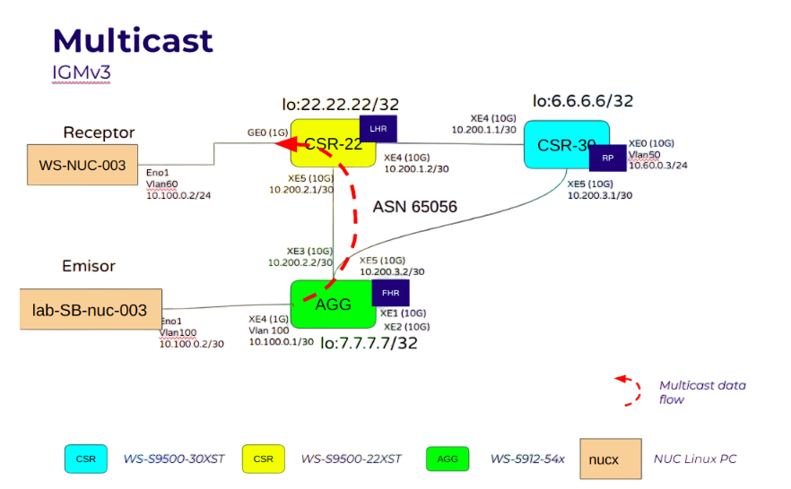
Multicast network was configured with the following information:
| Hostname | CSR22 | CSR30 | AGG |
|---|---|---|---|
|
Multicast Role |
Last Hop Router |
PIM Router |
First Hop Router
|
|
Multicast Configuration
|
ip multicast-routing
|
ip multicast-routing |
ip multicast-routing |
|
PIM Configuration |
ip pim rp-address 6.6.6.6 interface xe4 interface xe5 |
interface lo |
ip pim rp-address 6.6.6.6 interface xe3 interface xe5 |
|
Interface to Terminal |
interface ge0.100 |
|
interface xe32.100 |
For testing, the iperf version 2.0.13 software has been used as it is a simple and easily replicable tool that requires few resources to be deployed. The following table shows the flow description used:
| Hostname | Role | FLOW-ID | Multicast Group | BW [Mbps] | Iperf Command |
|---|---|---|---|---|---|
|
lab-SB-nuc-003
|
Sender |
Flow 1 |
230.10.10.10:5001 |
100 |
iperf -c 230.10.10.10 -u -T 10 -t 10000 -i 10 -b 100M |
|
WS-NUC-003 |
Receptor |
Flow 1 |
230.10.10.10:5001 |
100 |
iperf -s -u -B 230.10.10.10 -i 10 -H 10.100.100.2 -T 10
|
Once the flow was set up, we obtained the following results on the sender:
whitestack@lab-SB-nuc-003:~$ iperf -c 230.10.10.10 -u -T 10 -t 10000 -i 10 -b 100M
Client connecting to 230.10.10.10, UDP port 5001
Sending 1470 byte datagrams, IPG target: 112.15 us (kalman adjust)
Setting multicast TTL to 10
UDP buffer size: 208 KByte (default)
[ 3] local 10.100.100.2 port 47361 connected with 230.10.10.10 port 5001
[ ID] Interval Transfer Bandwidth
[ 3] 0.0-10.0 sec 125 MBytes 105 Mbits/sec
[ 3] 10.0-20.0 sec 125 MBytes 105 Mbits/sec
[ 3] 20.0-30.0 sec 125 MBytes 105 Mbits/sec
[ 3] 30.0-40.0 sec 125 MBytes 105 Mbits/sec
On the receiver, we obtained the following:
whitestack@WS-NUC-003:~$ iperf -s -u -B 230.10.10.10 -i 10 -H 10.100.100.2 -T 10
Server listening on UDP port 5001
Binding to local address 230.10.10.10
Joining multicast (S,G)=10.100.100.2,230.10.10.10
Receiving 1470 byte datagrams
UDP buffer size: 208 KByte (default)
[ 3] local 230.10.10.10 port 5001 connected with 10.100.100.2 port 47361
[ ID] Interval Transfer Bandwidth Jitter Lost/Total Datagrams
[ 3] 0.0-10.0 sec 125 MBytes 105 Mbits/sec 0.009 ms 1881/90980 (2.1%)
[ 3] 0.0000-10.0000 sec 14 datagrams received out-of-order
[ 3] 10.0-20.0 sec 125 MBytes 105 Mbits/sec 0.003 ms 0/89165 (0%)
[ 3] 20.0-30.0 sec 125 MBytes 105 Mbits/sec 0.004 ms 0/89164 (0%)
[ 3] 30.0-40.0 sec 125 MBytes 105 Mbits/sec 0.003 ms 0/89165 (0%)
| Hostname | CSR22 | CSR30 | AGG |
|---|---|---|---|
|
Multicast Routes |
show ip mroute IP Multicast Routing Table Flags: I – Immediate Stat, T – Timed Stat, F – Forwarder installed B – BIDIR Timers: Uptime/Stat Expiry Interface State: Interface (TTL) (10.100.100.2, 230.10.10.10), uptime 00:31:40, stat expires 00:02:53 Owner PIM, Flags: TF Incoming interface: xe5 Outgoing interface list: ge0.100 (1) |
show ip mroute IP Multicast Routing Table Flags: I – Immediate Stat, T – Timed Stat, F – Forwarder installed B – BIDIR Timers: Uptime/Stat Expiry Interface State: Interface (TTL |
show ip mroute IP Multicast Routing Table Flags: I – Immediate Stat, T – Timed Stat, F – Forwarder installed B – BIDIR Timers: Uptime/Stat Expiry Interface State: Interface (TTL) (10.100.100.2, 230.10.10.10), uptime 00:31:53, stat expires 00:03:18 Owner PIM, Flags: TF Incoming interface: xe32.100 Outgoing interface list: xe3 (1) |
|
PIM Neighbor and nexthop
|
show ip pim neighbor Neighbor Interface Uptime/Expires Ver DR Address Priority/Mode 10.200.1.1 xe4 02:20:40/00:01:35 v2 1 / 10.200.2.2 xe5 02:20:24/00:01:35 v2 1 / DR CSR-LAB-S9500-22XST# CSR-LAB-S9500-22XST# CSR-LAB-S9500-22XST#show ip pim nexthop Flags: N = New, R = RP, S = Source, M = MSDP Peer U = Unreachable Destination Type Nexthop Nexthop Nexthop Nexthop Metric Pref Refcnt Num Addr Ifindex Name
6.6.6.6 .R… 1 10.200.1.1 10005 xe4 2 110 2 10.100.100.2 ..S.. 1 10.200.2.2 10006 xe5 2 110 2 |
show ip pim neighbor Neighbor Interface Uptime/Expires Ver DR Address Priority/Mode 10.200.1.2 xe4 02:22:10/00:01:36 v2 1 / DR 10.200.3.2 xe5 02:23:55/00:01:22 v2 1 / DR
show ip pim nexthop No PIM next hops |
show ip pim neighbor Neighbor Interface Uptime/Expires Ver DR Address Priority/Mode 10.200.2.1 xe3 02:22:49/00:01:42 v2 1 / 10.200.3.1 xe5 02:24:34/00:01:41 v2 1 /
show ip pim nexthop Flags: N = New, R = RP, S = Source, M = MSDP Peer U = Unreachable Destination Type Nexthop Nexthop Nexthop Nexthop Metric Pref Refcnt Num Addr Ifindex Name
6.6.6.6 .R… 1 10.200.3.1 10005 xe5 2 110 3 10.100.100.2 ..S.. 1 0.0.0.0 328728676 xe32.100 3 1 2 |
L3VPN setup over SR
L3VPN services allow organizations to create a virtual private network between multiple sites, using a Layer 3 VPN.
L3VPN have standard configuration:
| Hostname | CSR22 | CSR30 | AGG |
|---|---|---|---|
|
VRF Definition |
ip vrf vrf1 |
ip vrf vrf |
ip vrf vrf1 |
|
BGP Configuration |
router bgp 65056 vrf1 |
router bgp 65056 redistribute connected |
router bgp 65056 neighbor 6.6.6.6 activate |
|
Access Interface |
interface ge0.350 |
interface xe10.250 |
interface xe32.150 |
For test connectivity and routing information, we have use Iperf in the same way that previous sections with 2 differents flows:
| Hostname | Role | FLOW-ID | Source | Destination | Protocol | BW | Iperf Command |
|---|---|---|---|---|---|---|---|
|
nuc1 |
Sender |
Flow 1 |
10.250.0.2 |
10.15.0.2 |
UDP |
300 |
iperf -c 10.15.0.2 -u -i 1 -t 600 -b 300M |
|
WS-NUC-003 |
Sender |
Flow 2 |
10.35.0.2 |
10.15.0.2 |
UDP
|
200 |
iperf -c 10.15.0.2 -u -i 1 -t 600 -b 200M |
|
nuc1 |
Receiver |
Flow 1 |
|
|
UDP |
|
iperf -s -u -i 1 -B 10.15.0.2 -e |
Senders:
whitestack@WS-NUC-003:~$ iperf -c 10.15.0.2 -u -i 1 -t 600 -b 200M
Client connecting to 10.15.0.2, UDP port 5001
Sending 1470 byte datagrams, IPG target: 56.08 us (kalman adjust)
UDP buffer size: 208 KByte (default)
[ 3] local 10.35.0.2 port 34621 connected with 10.15.0.2 port 5001
[ ID] Interval Transfer Bandwidth
[ 3] 0.0- 1.0 sec 25.0 MBytes 210 Mbits/sec
[ 3] 1.0- 2.0 sec 25.0 MBytes 210 Mbits/sec
[ 3] 2.0- 3.0 sec 25.0 MBytes 210 Mbits/sec
[ 3] 3.0- 4.0 sec 25.0 MBytes 210 Mbits/sec
[ 3] 4.0- 5.0 sec 25.0 MBytes 210 Mbits/sec
[ 3] 5.0- 6.0 sec 25.0 MBytes 210 Mbits/sec
[ 3] 6.0- 7.0 sec 25.0 MBytes 210 Mbits/sec
[ 3] 7.0- 8.0 sec 25.0 MBytes 210 Mbits/sec
[ 3] 8.0- 9.0 sec 25.0 MBytes 210 Mbits/sec
[ 3] 9.0-10.0 sec 25.0 MBytes 210 Mbits/sec
whitestack@nuc001:~$ iperf -c 10.15.0.2 -u -i 1 -t 600 -b 300M
Client connecting to 10.15.0.2, UDP port 5001
Sending 1470 byte datagrams, IPG target: 37.38 us (kalman adjust)
UDP buffer size: 208 KByte (default)
[ 3] local 10.250.0.2 port 41936 connected with 10.15.0.2 port 5001
[ ID] Interval Transfer Bandwidth
[ 3] 0.0- 1.0 sec 37.5 MBytes 315 Mbits/sec
[ 3] 1.0- 2.0 sec 37.5 MBytes 315 Mbits/sec
[ 3] 2.0- 3.0 sec 37.5 MBytes 315 Mbits/sec
[ 3] 3.0- 4.0 sec 37.5 MBytes 315 Mbits/sec
[ 3] 4.0- 5.0 sec 37.5 MBytes 315 Mbits/sec
[ 3] 5.0- 6.0 sec 37.5 MBytes 315 Mbits/sec
[ 3] 6.0- 7.0 sec 37.5 MBytes 315 Mbits/sec
[ 3] 7.0- 8.0 sec 37.5 MBytes 315 Mbits/sec
[ 3] 8.0- 9.0 sec 37.5 MBytes 315 Mbits/sec
[ 3] 9.0-10.0 sec 37.5 MBytes 315 Mbits/sec
And in the receiver:
whitestack@lab-SB-nuc-003:~$ iperf -s -u -i 1 -B 10.15.0.2 -e
Server listening on UDP port 5001 with pid 1865091
Binding to local address 10.15.0.2
Receiving 1470 byte datagrams
UDP buffer size: 208 KByte (default)
[ 3] local 10.15.0.2 port 5001 connected with 10.250.0.2 port 41936
[ ID] Interval Transfer Bandwidth Jitter Lost/Total Latency avg/min/max/stdev PPS NetPwr
[ 3] 0.0000-1.0000 sec 36.6 MBytes 307 Mbits/sec 0.051 ms 680/26805 (2.5%) -/-/-/- ms 26123 pps
[ 3] 1.0000-2.0000 sec 36.6 MBytes 307 Mbits/sec 0.050 ms 643/26749 (2.4%) -/-/-/- ms 26106 pps
[ 3] 2.0000-3.0000 sec 36.6 MBytes 307 Mbits/sec 0.238 ms 565/26690 (2.1%) -/-/-/- ms 26094 pps
[ 4] local 10.15.0.2 port 5001 connected with 10.35.0.2 port 34621
[ 3] 3.0000-4.0000 sec 36.7 MBytes 307 Mbits/sec 0.024 ms 661/26807 (2.5%) -/-/-/- ms 26178 pps
[ 4] 0.0000-1.0000 sec 24.4 MBytes 205 Mbits/sec 0.020 ms 458/17856 (2.6%) -6.022/-6.085/-2.545/ 0.167 ms 17397 pps 0.00
[ 3] 4.0000-5.0000 sec 36.6 MBytes 307 Mbits/sec 0.027 ms 676/26748 (2.5%) -/-/-/- ms 26072 pps
[ 4] 1.0000-2.0000 sec 24.4 MBytes 205 Mbits/sec 0.015 ms 394/17833 (2.2%) -6.027/-6.088/-2.590/ 0.145 ms 17438 pps 0.00
[ 3] 5.0000-6.0000 sec 36.6 MBytes 307 Mbits/sec 0.012 ms 671/26750 (2.5%) -/-/-/- ms 26079 pps
[ 4] 2.0000-3.0000 sec 24.3 MBytes 204 Mbits/sec 0.016 ms 479/17832 (2.7%) -6.011/-6.086/-2.540/ 0.179 ms 17354 pps 0.00
[ 3] 6.0000-7.0000 sec 36.5 MBytes 306 Mbits/sec 0.012 ms 691/26749 (2.6%) -/-/-/- ms 26058 pps
[ 4] 3.0000-4.0000 sec 24.4 MBytes 204 Mbits/sec 0.018 ms 453/17835 (2.5%) -6.002/-6.090/-2.564/ 0.190 ms 17381 pps 0.00
[ 3] 7.0000-8.0000 sec 36.6 MBytes 307 Mbits/sec 0.040 ms 674/26749 (2.5%) -/-/-/- ms 26076 pps
and checking the traffic in the interfaces of the router:
LAB-WSCL-PE001#show interface counters rate mbps
+——————-+————–+————-+————–+————-+
| Interface | Rx mbps | Rx pps | Tx mbps | Tx pps |
+——————-+————–+————-+————–+————-+
po13 0.00 2 0.00 2
po23 0.00 3 0.00 3
xe3 217.43 17834 0.00 0
xe5 326.14 26750 0.00 0
xe32 0.01 15 542.14 44583
xe41 0.00 0 0.00 1
xe42 0.00 1 0.00 1
xe43 0.00 1 0.00 1
xe44 0.00 1 0.00 2
LAB-WSCL-PE001#
And for check the status of L3VPN over the network:
| Hostname | CSR22 | CSR30 | AGG |
|---|---|---|---|
|
VRF Routes |
CSR-LAB-S9500-22XST#show ip route vrf vrf1 database IP Route Table for VRF “vrf1”
|
CSR-LAB-S9500-30XS#show ip route vrf vrf1 database Gateway of last resort is not set |
LAB-WSCL-PE001#show ip route vrf vrf1 database IP Route Table for VRF “vrf1” C *> 10.15.0.0/30 is directly connected, xe32.150, 05:59:38 |
Conclusion
In conclusion, organizations should seriously consider migrating from MPLS LDP to Segment Routing (SR) in open networking devices, given the advantages such as better utilization of physical space, higher capacity of switching, and lower power consumption that open architectures bring. Additionally, this migration does not require major upgrades, as it can co-exist with MPLS and can be smoothly transitioned to SR.
SR provides organizations with significant improvements over MPLS LDP, including enhanced performance, scalability, and ease of management. The key services (currently running on MPLS) can be configured using SR, offering organizations the flexibility and scalability they need to meet the demands of their networks. This allows for a seamless transition without disrupting the provisioning of the network, enabling continuity of customer and network operations and the transparent adoption of new technology.
About the Author
Claudio Avila is an Electronic Engineer from Chile, and has more than 16 years of experience in different roles and positions in Telecom Industry with experience in rollout, analysis, test and design IP networks in LATAM. Currently, he is a Technical Solution Architect in Whitestack for Open Networking. This article was reviewed by Gianpietro Lavado, co-founder of Whitestack and Cisco CCIE.